Introduction to Gas Turbines

General, Functional Description

 A package power plant, as furnished for most installations, is comprised of the single-shaft, simple cycle, heavy duty gas turbine unit driving a generator. Fuel and air are used by the gas turbine unit to produce the shaft horsepower necessary to drive certain accessories and ultimately the driven load generator.

The turbine unit is composed of a starting device, support systems, an axial-flow compressor, combustion system components, a three-stage turbine. Both compressor and turbine are directly connected with an in-line, single-shaft rotor supported by two pressure lubricated bearings. The inlet end of the rotor shaft is coupled to an accessory gear having integral shafts that drive the fuel pump, lubrication pump, and other system components.

About Gas Turbine Units

When the turbine starting system is actuated and the clutch is engaged, ambient air is drawn through the inlet plenum assembly, filtered, then compressed in the 17th stage, axial flow Compressor. For pulsation protection during start-up, the 11th stage extraction valves are open and the variable inlet guide vanes are in the closed position. When the speed relay corresponding to 95 per cent speed actuates, the 11th stage extraction bleed valves close automatically and the variable inlet guide vane actuator energizes to open the inlet guide vanes (I.G.V.) to the normal turbine operating position.
Compressed air from the compressor flows into the annular space surrounding the fourteen combustion chambers, from which it flows into the spaces between the outer combustion casings and the combustion liners.

The fuel nozzles introduce the fuel into each of the fourteen combustion chambers where it mixes with the combustion air and is ignited by both (or one, which is sufficient) of the two spark plugs.

At the instant one or both of the two spark plugs equipped combustion chambers is ignited, the remaining combustion chambers are also ignited by crossfire tubes that connect the reaction zones of the combustion chambers. After the turbine rotor approximates operating speed, combustion chamber pressure causes the spark plugs to retract to remove their electrodes from the hot flame zone.

The hot gases from the combustion chambers expand into the fourteen separate transition pieces attached to the aft end of the combustion chamber liners and flow towards the three stage turbine section of the machine. Each stage consists of a row of fixed nozzles followed by a row of rotatable turbine buckets. In each nozzle row, the kinetic energy of the jet is increased, with an associated pressure drop, and in each following row of moving buckets, a portion of the kinetic energy of the jet is absorbed as useful work on the turbine rotor.

After passing through the 3rd stage buckets, the exhaust gases are directed into the exhaust hood and diffuser which contains a series of turning vanes to turn the gases from the axial direction to a radial direction, thereby minimizing exhaust hood losses. Then, the gases pass into the exhaust plenum.

The resultant shaft rotation is used to turn the generator rotor, and drive certain accessories.


Design Basis

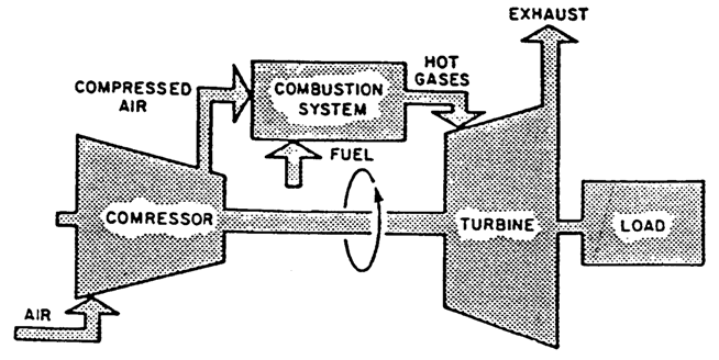
Simple Cycle Gas Turbine Flow Diagram


The turbine unit is composed of a starting device, support systems, an axial-flow compressor, combustion system components, a three-stage turbine. Both compressor and turbine are directly connected with an in-line, single-shaft rotor supported by two pressure lubricated bearings. The inlet end of the rotor shaft is coupled to an accessory gear having integral shafts that drive the fuel pump, lubrication pump, and other system components.


Gas Turbine Lubrication System

NOTE: Lubricating oil recommendations are included in the "Gas turbine subcontractor’s Literature chapter".

The lubricating requirements for the gas turbine power plant are furnished by a common forced-feed lubrication system. This lubrication system, complete with tank, pumps, coolers, filters, valves and various control and protection devices, furnishes normal lubrication and absorption of heat rejection load of the gas turbine. Lubricating fluid is circulated to the three main turbine bearings, generator bearings, and to the turbine accessory gear and fuel pump. Also, lubricating fluid is supplied to the starting means torque converter for use as hydraulic fluid as well as for lubrication. Additionally, a portion of the pressurized fluid is diverted and filtered again for use by hydraulic control devices as control fluid.

Major system components include:
  • Lube reservoir in the accessory base;
  • Main lube pump (shaft driven from the accessory gear);
  • Auxiliary lube pump and emergency lube pump;
  • Pressure relief valve VR-1 in the main pump discharge;
  • Lube fluid heat exchanger;
  • Lube filters;
  • Bearing header pressure regulator VPR-2-1.
Lube fluid temperatures are indicated on the thermocouples which may be located in the bearing header, bearing drains, and the oil tank. For turbine starting, a maximum of 800 SSU is specified for reliable operation of the control system and for bearing lubrication. A thermocouple, LT_OT-1A, prevents turbine start-up if the temperature of the lubricant is lower than the switch setting (only if applicable).

Lubricating fluid for the main, auxiliary and emergency pumps is supplied from the reservoir, While lubricating fluid used for control is supplied from the bearing header. This lubricant must be regulated to the proper, predetermined pressure to meet the requirements of the main bearings and the accessory lube system, as well as the hydraulic control and trip circuits.

Regulating devices are shown on the Lube System Schematic Diagram Figure LS-1. All lubricating fluid is filtered and cooled before being piped to the bearing header.

The reservoir for the lubrication system is the 3300 gallon (i.e. 12 491 l) tank which is fabricated as an integral part of the accessory base. Lubricating fluid is pumped from the reservoir by the main shaft driven pump (part of the accessory gear) or auxiliary or emergency Pumps at a pressure of 25 psig (i.e. 1.75 bar) to the bearing header, the accessory gear and The hydraulic supply system. After lubricating the bearings the lubricant flows back through various drain lines to the lube reservoir.

All lubricant pumped from the lube reservoir to the bearing header flows through the lube fluid heat exchanger(s) to remove excess heat and then through the cartridge type filters providing five micron filtration. The dual heat exchangers are connected in parallel.

Filtration of all lube oil is accomplished by a 5 micron, pleated paper filter installed in the lube system just after the lube oil heat exchanger. Two filters are used with a transfer valve installed between the filters to direct oil flow through either filter and into the lube oil header.


 Lubricating Oil Pumps 

Lubrication to the bearing header is supplied by three lube pumps:

1-The main lube supply pump is a positive displacement type pump mounted in and driven by the accessory gear.

2 -The auxiliary lube supply pump is a submerged centrifugal pump driven by an A.C. motor.

3 -The emergency lube supply pump is a submerged centrifugal pump driven by a D.C. motor.


Main Lube Pump
The main lube pump is built into the inboard wall of the lower half casing of the accessory gear. It is driven by a splined quill shaft from the lower drive gear. The output pressure to the lubrication system is limited by a back-pressure valve to maintain system pressure.

Auxiliary Lube Pump
The auxiliary lube pump is a submerged centrifugal type pump driven by an A.C. motor. It provides lubricant pressure during start-up and shut-down of the gas turbine when the main pump cannot supply sufficient pressure for safe operation. Operation of this pump is as follows:

The auxiliary lube pump is controlled by a low lube oil pressure alarm switch (63 QA-2). This low pressure level alarm causes the auxiliary pump to run under low lube oil pressure conditions as is the case during start-up or shut down of the gas turbine when the main pump, driven by the accessory drive device, does not supply sufficient pressure. At turbine start-up, the A.C. pump starts automatically when the master control switch on the turbine control panel is turned to the START position.

The auxiliary pump continues to operate until the turbine reaches approximately 95 per cent of operational speed.

At this point, the auxiliary (cooldown) lube pump shuts down and system pressure is supplied by the shaft-driven, main lube pump.

During the turbine starting sequence, the pump starts when the start signal is given. The control circuit is through the pressure level of pressure switch 63 QA-2. The pump will run until the turbine operating speed is reached (operating speed relay 14 HS picks up), even though the lube oil header is at rated pressure and the discharge pressure level (63 QA-2) is above alarm level setting.

When the turbine is on the shut-down sequence, this pressure transmitter will signal for the auxiliary pump to start running when the lube oil header pressure falls to the point at which pressure level alarm setting is reached.

Emergency Lube Pump
The emergency lube pump is a D.C., motor-driven pump, of the submerged centrifugal type. This pump supplies lube oil to the main bearing header during an emergency shutdown In the event the auxiliary pump has been forced out of service because of loss of A.C. power, or for other reasons. It operates as follows:

This pump is started automatically by the action of pressure transmitter 96 QA-2 whenever the lube pressure in the main bearing header falls below the pressure switch set ting.

Should the auxiliary pump fail during the shut-down sequence, because of an A.C. power failure or any other cause, the emergency lube pump will be started automatically by the action of low lube oil pressure transmitter 96 QA-2 and continue to run until the turbine shaft comes to rest.

Gas Turbine Heat Exchanger and Filters

Lube Fluid Heat Exchanger

The heat exchanger system is required to dissipate the heat absorbed by the lubricating fluid and to maintain the fluid at the proper bearing header temperature. This is accomplished by circulating cooling water through the cooling tubes of the heat exchanger as the lubricant flows over the tubes. Cooling water flow through the heat exchanger is controlled by temperature sensitive flow regulator valve VTR 1, that maintains the correct bearing temperature.

(See Cooling water system for information on this regulator valve). The lube fluid heat exchanger system uses a fluid-to-water cooler of the shell and tube bundle design. There is one heat exchanger, flange mounted in the lube reservoir in a horizontal position. A U-tube bundle extends into the center of the shell through which the cooling water is passed. The lube fluid flows in and out of the shell ; passing over the cooling tubes of the tube bundle. Cooling water connections are made at the external steel bonnet that bolts to the shell mounting flange through the tube sheet that supports the tubes of the tube bundle.


Filters

Main lube filtering system - Filtration of all lube oil is accomplished by a 5 micron, pleated paper filter installed in the lube system just after the lube oil heat exchanger.

One (duplex) filter is used with a transfer valve installed between the filters to direct oil flow through either filter and into the lube oil header.

The dual filters arranged side by side, are installed on the tank and connected into the pump discharge header through a manual transfer valve. Only one filter will be in service at a time, thus cleaning, inspection, and maintenance of the second one can be performed without interrupting oil flow or shutting the gas turbine down. By means of the manually operated, worm-driven transfer valve, one filter can be put into service as the second is taken out, without interrupting the oil flow to the main tube oil header. The transfer of operation from one filter to the other should be accomplished as follows:

1 -Open the filler valve and fill the standby filter until a solid oil flow can be seen in the flow sight in the filter vent pipe. This will indicate a "filled" condition.

2 -Operate the transfer valve with a wrench to bring the standby filter into service.

3 -Close the filler valve.

Filters should be changed when the differential pressure switch 63 QQ-1 indicates a differential pressure of 15 psig (i.e. about 1.03 bar). Refer to the "Gas turbine maintenance guide chapter" for inspection schedules. An alarm from 63 QQ-1 signals when the differential pressure exceeds 15 psig.

NOTE: For the detailed drawing of the lube oil system circuit and the settings, see "Gas turbine operation guide chapter”: Piping systems schematic.


Gas Turbine Cooling Water System

General

The cooling water system is a pressurized, closed system, designed to accommodate the heat dissipation requirements of the turbine, the lubrication system, the turbine support legs and the flame detector mounts. An aqueous solution of ethylene glycol is used in the system; therefore, it is capable of performing its function throughout the year if the ambient temperatures are not too high. During frost the cooling system must be filled with an aqueous solution of ethylene glycol. During high temperatures it is necessary to fill the system with a solution whose quality is specified in the "Gas turbine subcontractor’s literature chapter". In the text that follows, this solution is referred to as the cooling water.

Included in the cooling water system are the cooling cells, the pumps, miscellaneous valves and certain control and protection devices. The cooling system is connected to the customer's cooling water system.


Functional Description

The cooling water system circulates water as a cooling medium to maintain the lubricating oil at acceptable lubrication system temperature levels and to cool several turbine components. The system normally operates at a slightly positive pressure which results when the fuel in the system expands with the increase in temperature during operation.

During operation the coolant is supplied by the owner's cooling system and circulates through the chosen lube oil, the turbine support legs (in parallel with the system of heat exchanger) and the flame detector mounts. After absorbing the heat rejected by these items, the coolant flows through the owner's water cooling system where it is cooled.

The flame detector mounts are cooled to extend the life of the flame detectors. The coolant jackets on the flame detector mounts provide a thermal break in the heat conduction from the combustor can housing to the flame detector instrument.


Flow regulating valves


The coolant circuit for the lube oil has a temperature actuated 3-way valve (VTR-1) installed in the coolant inlet line to the heat exchanger.

This type of valve, which controls coolant flow to the heat exchanger, has a manually operated device which can override the thermal element. The manual override device should be used only when the valve's thermal element is inoperative but machine operation is required. Lube Oil feed header temperature is sensed by the bulb associated with the valve which controls the flow of coolant through the heat exchanger and maintains the lube oil temperatures at predetermined values. The valve automatically controls flow of the medium passing through it (coolant) to the heat exchanger by responding to temperature changes affecting the bulb.

The bulb contains a thermal-sensitive liquid which vaporizes when heated. Pressure thus generated in the bulb is transmitted through the capillary tube to the bellows, which positions the valve disc to control the flow of coolant through the heat exchanger. The valve is closed during turbine startup, and will start to open as the sensed fluid temperature approaches the control setting.

At the inlet of each cooling water circuit (lube oil heat exchanger circuit and turbine support legs circuit), an orifice allows water flow rate calibration to the circuit concerned.


Shut-off valves

Shut-off valves are provided in the piping so that the tube side of the lube oil heat exchanger may be isolated from the water system for maintenance.

Temperature, pressure measuring and/or protective devices Thermocouples, WT_TL-1,-2 at turbine support legs outlet located at GT cooling system outlet, give a GT cooling water temperature indication.

NOTE: For the recommendations about the various components of the circuits, refer to The "Gas turbine subcontractor’s literature chapter".